Therefore, if the output voltage v o is required to be kept constant, due to the dc input voltage variations or voltage drops within the power circuit, this is achieved through the pulse width variations of the gating signals and, consequently, the output voltage pulse widths.įigure 6.2. When the output voltage is required to be decreased, then the conduction time intervals of S 1 and S 2 are decreased. When an increase is required in the output voltage, then the conduction time intervals of S 1 and S 2 are increased. The output voltage control can be achieved by varying the pulse widths of the output voltage through the gating signals of the semiconductor switches. When S 2 or D 2 is conducting, the output voltage is v o = −V in/2. When S 1 or D 1 is conducting, the output voltage is v o = V in/2. As shown in Fig. 6.2(d) the output voltage v o is a two-level square-wave pulse (V in/2 and −V in/2). The freewheeling diodes across the switches are included in the same power module as the switches. The choice of the semiconductor switches for implementing this inverter depends on its power and switching requirements. Quickly thinking about it, while the results are the same and you don't get frequency shifting, one has included or will be using a second oscillator in the process of frequency shifting rather than trying to perhaps save a VCO with a sub osc.Fig. 6.2 shows the power circuit and the generated output voltage of a single-phase half-bridge inverter. A frequency shifter in analog hardware is going to need a sine wave oscillator either built into the frequency shifter or in the case of rarer even more costly units an external source and extra circuitry.


Think about early Japanese monosynths and their budget inclusion of sub oscillators rather than second oscillators, a frequency shifter back in the day cost way more than that Roland monosynth did.

It's likely not generating something comparable to a suboscillator. Though also as sort of pointed out it gets trickier to do a great octave pedal versus taking a VCO waveform and doing a divide on it which is super simple.Ī frequency shifter is going to alter the harmonic relationship of the harmonics in the sound as they are shifted. Interesting but sort of self defeating question once one looks into what's involved with a frequency shifter.Īgreed, with a traditional analog suboscillator design one can very inexpensively in terms of hardware create a square wave an octave under the source. So, fortunately or unfortunately, there is no best in this case.
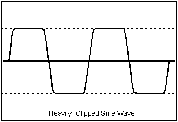
HARMONICS OF A BIPOLAR SQUARE WAVE PATCH
You could patch this with a standard divider and VC polarizer. The technique involves generating a sub-octave square and using this to flip the phase of your input every other cycle. Most octave pedals for guitar and bass use this principal (see OC-2). There are a few analog octave divider circuits that attempt to maintain a sound similar to your input but an octave or two lower. Most modular octave dividers are based on the concept of the flip-flop, so the output will typically be a 50% duty cycle square wave. The result is a sound that's timbrally pretty close to your original signal, only shifted in pitch. Pitch shifting shifts all the harmonics proportionally, so that the relative tuning of harmonics stays the same. As a result, shifting by a large amount like an octave will create a sound more like ring modulation (but with only one sideband) than an octave divider.

This means that harmonics become increasingly inharmonic the more you shift the fundamental frequency. Frequency shifters shift all frequencies in a signal by the same amount on a linear scale.


 0 kommentar(er)
